
1-805-484-2992
Quotes - Engineering - SalesWhat changes when one side boils or condenses
A two-phase brazed plate exchanger has a liquid on one side and a refrigerant changing phase on the other: boiling in an evaporator, condensing in a condenser. The 316L plate stack and the vacuum braze are the same as on a liquid-to-liquid unit, but three things in the construction change, and getting them right is the difference between a chiller that holds its capacity and one that hunts, floods or freezes a plate. The three are the way refrigerant is distributed at the inlet, the channel geometry, and the direction the refrigerant travels relative to the water.
Distribution first. Refrigerant leaves the expansion valve as a two-phase mix, roughly 15–30 percent flash gas by mass but most of the volume. Fed straight into a port, the gas takes the nearest channels and the liquid runs to the far end of the stack, so the front plates superheat early and the back plates flood. An evaporator pack therefore carries a distribution device inside the refrigerant inlet port, an orifice tube or drilled insert that meters an even share of liquid into every channel. A condenser needs none: vapor enters at the top, condenses on the cold plate, and the liquid drains to the bottom port under gravity.
Channel geometry second. Refrigerant charge, vapor velocity and water-side pressure drop pull different ways, so many two-phase plate designs are asymmetric, with each channel sized for its own fluid. Direction third: in an evaporator the refrigerant enters at the bottom and rises as it boils; in a condenser it enters at the top and falls as it condenses; the water runs the opposite way in both. Pipe a condenser with vapor at the bottom and liquid backs up over the plates. The pressure rating follows the refrigerant: 435–650 psig covers HFC and HFO blends at normal condensing temperatures, and transcritical CO2 needs a plate design rated to 140 bar, about 2,030 psig.
316L plates with copper braze cover HFC and HFO refrigerants; ammonia takes nickel braze, and transcritical CO2 takes a plate design rated to 140 bar. See Material & Construction for the grade comparison.
Evaporator, condenser and the freeze line
Built as an evaporator
- Distribution insert in the refrigerant inlet port; refrigerant up, water down
- Superheat set by the expansion valve, typically 8–12°F; the pack holds little refrigerant, so the valve must be stable
- Leaving water below about 40°F needs glycol or a proven freeze guard
- Oil returns with the vapor only while channel velocity holds at part load
Built as a condenser
- Vapor in at the top port, liquid out at the bottom, water in counterflow
- Subcooling of 5–10°F comes from the lowest plates sitting in liquid
- Tower water on the cold side means a strainer and a chloride check on 316L
- Discharge gas near 200°F sits comfortably inside the 400°F plate envelope
Freeze protection, the mistake we see
- Throttling water flow to raise the temperature rise: the plate next to boiling refrigerant drops below 32°F
- A frozen channel splits the plate at the braze line and puts water into the refrigerant circuit
- Flow switch, low-pressure cutout and a leaving-water low limit are the three guards
- 25–35% glycol is the fix for anything leaving below 40°F
Two-phase build at a glance
Standard values; the quotation fixes them for your refrigerant and capacity.
| Feature | Typical build |
| Plates | 316L chevron, asymmetric channels where charge and pressure drop call for them |
| Braze | Copper for HFC and HFO; nickel for ammonia; CO2 designs copper brazed on heavier plates |
| Refrigerant pressure | 435–650 psig; 2,030 psig (140 bar) on transcritical CO2 designs |
| Temperature envelope | -320 to 400°F; hot gas at discharge temperature is inside it |
| Evaporator inlet | Distribution insert in the refrigerant port; bottom in, top out |
| Condenser inlet | Vapor top in, liquid bottom out; subcooling from the flooded lower plates |
| Water side | Counterflow to the refrigerant; strainer on open water; glycol when leaving below 40°F |
| Connections | Copper or stainless stubs for brazing on the refrigerant side; threaded or flanged water ports |
| Circuits | One; two refrigerant circuits on one water side for staged chillers |
Questions on boiling and condensing in a plate pack
A shell-and-tube DX evaporator feeds its tubes through a distribution head with a long run before the bundle, and the tube count is small. A plate pack may have 40–100 refrigerant channels fed from one port a few inches long, and the two-phase mix separates in that port. The insert meters liquid into each channel; without it the first channels run dry and the last ones flood, and the measured capacity falls short of the plate area.
Yes, with a compromise. In heating mode the refrigerant condenses, in cooling mode it boils, and the port direction that is right for one is wrong for the other. The reversible design accepts a slightly poorer condensing performence so that the evaporating mode, which carries the freeze risk, is piped correctly. The distribution insert stays in place and is sized for the evaporating duty.
Keep the leaving water at or above 40°F and the design water flow in place, and a plain-water evaporator is usually safe with a flow switch and low-pressure cutout. Below 40°F leaving, or on any system that throttles water flow at part load, the channel wall near the refrigerant inlet reaches 32°F before the bulk water does. That is where 25–35% glycol stops being optional.
It changes the braze and the connections, not the plate. Ammonia attacks copper, so the pack is nickel brazed and the stubs are stainless; a copper-brazed evaporator on ammonia fails at the joints. The 316L plate is unaffected by ammonia. Flooded operation is common on ammonia plate evaporators, which removes the distribution insert and the superheat question but adds a surge drum to the design.
8–12°F is the usual target. A plate pack has very little refrigerant charge, so it responds to the expansion valve far faster than a shell-and-tube bundle, and a valve tuned for the bundle hunts. An electronic valve or a thermostatic valve with the bulb on a clean, insulated length of suction line settles it. Hunting shows up as capacity swings and, at the low end, as liquid in the suction.
Related
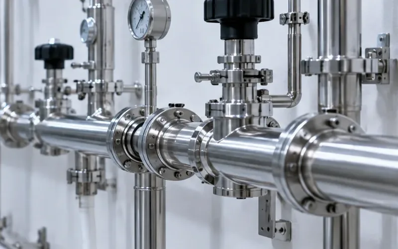
Brazed Plate
All-Stainless
Every wetted surface stainless, joints included. When corrosive, high-purity or copper-free food liquids rule out copper and nickel braze, this is the plate pack.
+ Learn More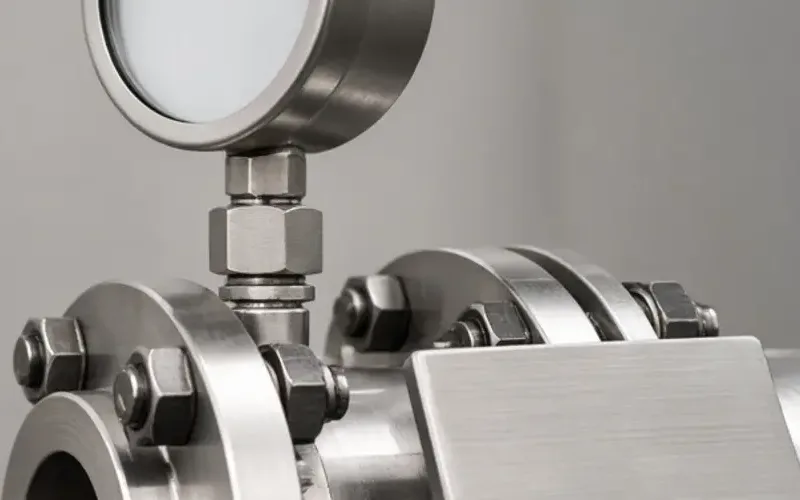
Brazed Plate
316L Plates
Copper brazed versus stainless brazed is a filler question, not a plate question. What the 316L plate tolerates, and what each braze adds or takes away.
+ Learn More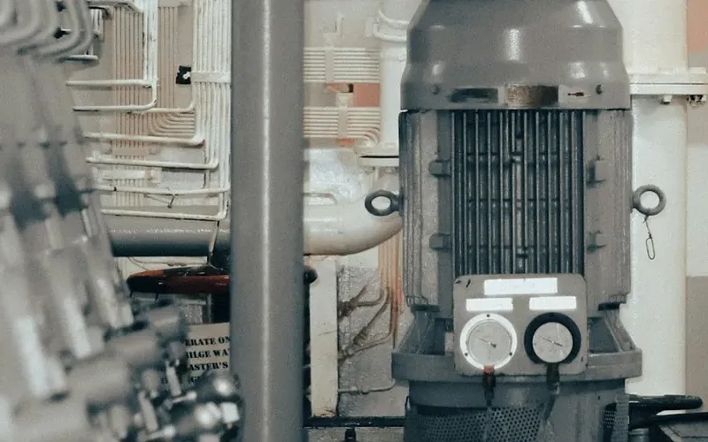
Brazed Plate
Single Phase
How a liquid-to-liquid brazed plate pack is put together: chevron plates, channel gap, port pattern, and the braze filler that the fluid decides.
+ Learn More