
1-805-484-2992
Quotes - Engineering - SalesWhat size shell and tube do you need?
Four quantities set the surface
Sizing starts with the duty: Q equals flow times specific heat times temperature change. For water that reduces to gpm × 500 × temperature change in °F, giving Btu/h, so 50 gpm cooled through 30°F is 50 × 500 × 30 = 750,000 Btu/h. The surface then follows from A = Q / (U × LMTD × F): the duty divided by the overall coefficient U, the log mean temperature difference, and a correction factor F for multi-pass flow.
U is built from the film coefficient on each side, the resistance of the tube wall and a fouling factor for each fluid. The film coefficients depend on velocity, viscosity and conductivity, which is why the tube count, passes and baffle spacing are chosen together with the surface rather than after it. Pressure drop is the constraint that stops velocity being raised without limit.
Grade enters the sizing through wall resistance: 304L and 316L conduct about 9.4 Btu/h-ft-°F, so a stainless bundle carries more surface than copper would for the same duty. Grade limits are set out on Material & Construction.
Stainless adds one term that matters. A 0.065 in. wall of 316L, at about 9.4 Btu/h-ft-°F, has a resistance of about 0.00058 h·ft²·°F/Btu, the same order as a water fouling factor, while the same copper wall at about 230 is near 0.00002. A stainless bundle therefore carries more surface for the same duty, and a thinner tube wall recovers some of it.
Shell & Tube Construction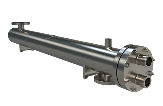
Worked example: steam heating water in 316L tubes
Illustrative only. The real selection is run on rating software against the actual fluids, with film coefficients calculated rather than assumed, and no performance is promised from this arithmetic.
| Condition | Typical value |
| Duty | 60 gpm × 500 × 80°F = 2,400,000 Btu/h |
| Water side | 60 gpm heated from 60°F to 140°F in 316L tubes |
| Steam side | 15 psig saturated steam on the shell, condensing at 250°F; about 2,540 lb/h |
| LMTD | End differences of 190°F and 110°F give about 146°F; F = 1 with condensing steam |
| Clean U, assumed | 400 Btu/h·ft²·°F for this illustration |
| Fouling factor | 0.001 h·ft²·°F/Btu on the water side, giving a design U of about 286 |
| Surface required | 2,400,000 / (286 × 146) = about 57 ft² |
| Without fouling | About 41 ft²; the fouling factor adds about 40% surface |
| One layout | 38 tubes, 3/4 in. OD, 16 BWG, 8 ft, two passes: about 60 ft² at roughly 3.4 ft/s |
Log mean temperature difference: the effective driving force between the hot and cold streams, found from the temperature difference at each end of the exchanger as the larger minus the smaller, divided by the natural log of their ratio. Multi-pass shells multiply it by a correction factor F, usually kept above about 0.8.
How a shell and tube sizing is run
What to send
A sizing needs both fluids, both flows and enough temperatures to close the heat balance: both flows and three of the four temperatures, or one flow and all four. Everything else shapes the selection.
- Fluids, with concentration, viscosity and specific heat if not water, glycol or steam
- Flows and inlet and outlet temperatures on each side
- Operating and design pressure and temperature, and allowable pressure drop, each side
- Chloride, pH, solids and fouling history, which set the grade and fouling factor
- Codes, connections, orientation and the space available, including pull clearance
From duty to surface
With one stream condensing, F is 1 and the LMTD stands as calculated. With two liquids in a shell with two or more tube passes, the streams are partly in paralell flow and F falls below 1; when it drops under about 0.8, or the outlet temperatures cross, the selection moves to shells in series or a counterflow arrangement. Fouling factors of 0.001–0.002 h·ft²·°F/Btu are common for tower water and process liquids, and they are applied per side, not stacked on a percentage margin.
Passes, baffles, tube size and length
Tube passes set tube-side velocity: water is kept at about 3–8 ft/s, the low end where erosion is a concern and the high end for fouling control. More passes raise velocity and the film coefficient and also pressure drop, which rises roughly with the square of velocity. Baffle spacing and cut do the same job on the shell side. Tubes of 3/4 in. or 1 in. OD are common, 5/8 in. in compact units, and a longer, slimmer shell is usually cheaper per square foot if the plant can give it the length and the pull space.
The mistake: margin piled on margin
An inquiry that asks for a 0.002 fouling factor, 25% excess surface and the highest flow the plant might ever see gets a unit that runs at low velocity in normal service. Low velocity fouls faster, so the oversizing creates the fouling it was meant to cover. State the normal duty, the worst realistic case and the fouling history, and let one fouling factor carry the margin. When you are ready, send the duty for a quote.
Questions on sizing a stainless bundle
That depends on duty, temperature difference and U, not on pipe size or flow alone. Work out the duty from flow and temperature change, then the LMTD from the four temperatures; with a typical stainless steam-to-water U in the low hundreds, the surface follows. The worked example on this page lands near 57 ft² for 2,400,000 Btu/h.
Because the wall itself resists heat flow. At about 9.4 Btu/h-ft-°F against roughly 230 for copper, a 0.065 in. stainless wall adds a resistance comparable to a fouling factor. The difference is largest on duties where both film coefficients are high, such as condensing steam against fast-moving water, and smallest where a viscous fluid controls U.
For tower water and most process liquids, 0.001–0.002 h·ft²·°F/Btu on that side, lower for clean closed loops and condensing steam. Choose from your own cleaning history where you have it. Specify the fouling factor or a surface margin, not both, because stacking them oversizes the unit and slows the fluid enough to foul it faster.
Yes, if both flows are known: the heat balance gives the fourth temperature, since the heat lost by one stream equals the heat gained by the other. With only one flow, all four temperatures are needed so the other flow can be calculated. With fewer data than that, the duty is not defined.
Related
Shell & Tube
Polished & Electropolished
Which surfaces of a stainless shell and tube need a finish, what 32, 20 and 15 microinch Ra mean, and how electropolishing and passivation differ.
+ Learn More
Shell & Tube
316L Stainless
Where 316L belongs in a shell and tube, part by part: tubes, tubesheet, shell and heads, with the chloride and temperature limits that decide each one.
+ Learn More
Shell & Tube
304L Stainless
When 304L tubes, tubesheets and shells do the job at lower cost: clean steam, glycol, low-chloride water and nitric service, and the duties that need 316L.
+ Learn More